
LED Locomotive Headlight Replacement
Thank you to Tom from California for this great and very informative article!
Tom tells us he did the installation and took all of the photos in one evening....
Replacing the Incandescent Light Bulb
with an LED in the Accucraft Pyle Headlight Housing
Miniature light bulbs are subject to bumps and vibrations, current variations and have a limited useful life. LEDs [light emitting diodes] on the other hand have proven to be successful in replacing standard light bulbs and now are very bright. One problem is how to get one, along with the associated electronics, inside a headlight housing. Fortunately, Evans Design has made a kit which can be used to place a bright LED inside the Accucraft Pyle National headlight housing while hiding the electronics inside the smoke box. The use of a 5 mm warm white high intensity LED makes the light a focused headlight which shines brightly down the track similar to the prototype.
The installation of the kit is very simple and can be performed in any of the Accucraft D & RG (and C & S #60) locomotives. It may be applicable for their other locos as well as other brands of large scale equipment. For the Accucraft locos, the C-16 and K-27 were the early models in which the power transmission and pick-up was done using the traditional brass model approach where the loco picked up one side of the rail and the tender was the other pick-up. The drawbar between the loco and tender was also the connection for the motor and lighting system. Underneath the cab is a four wire junction block where both sides of the track power were used to power the motor and lights. In the smoke box there is a small constant lighting circuit which powered the headlight, marker lights, and the interior cab light. Since the Evans LED system can run from the track (DC, DCC or battery) power over the complete range, tapping the wire leads leading to the constant lighting circuit in the smoke box will power the LED circuit.
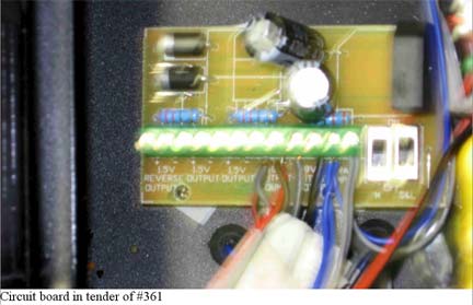
For the newer locos, Accucraft replaced the drawbar electrical connection with an 8 wire connector between the loco and tender. All track power pick-ups run to a circuit board in the tender. From this board are junction blocks for motor power, power for the sound system, and three 1.5 volt constant lighting circuits. In this case the brown and gray wires from one of the lighting circuits are used to power the headlight and marker lights in the loco as well as the cab light. I switched the gray and brown wires to the full current output terminals of the circuit board to be able to run the full current to the smoke box. I installed my own constant lighting circuit in the smoke box for the marker lights. The gray and brown wires were used as the input lines for the LED lighting circuit as well as the constant lighting circuit.
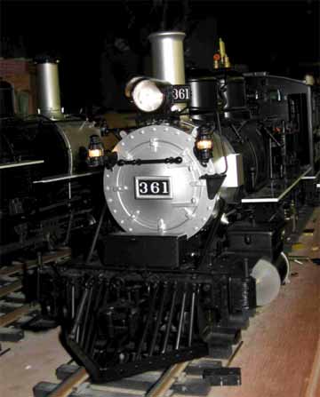
LGB Locomotive #361 prior to installation of LEDs (the train is lit up)
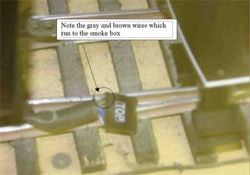
Connector between loco and tender on Locomotive #361
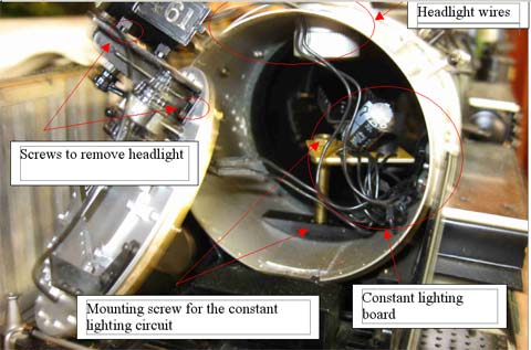
Installation of the LED in the headlight is reasonably simple. The most critical part for me was handling the tiny 2 mm screws. There are five 2 mm screws that hold the headlight to the top (or front) of the smoke box; two on either side. The fifth screw holds the hand rail from the step on the front of the smoke box that runs to the headlight platform. Remove these screws and carefully store them in a safe place. See above photos where screws are highlighted for the #461 and below on the #361.
The smoke box front may be removed in either of two ways. Older locos (C-16, C & S # 60 and the K-27s) may be just pulled out. The newer locos have a small 2 mm screw on either side of the smoke box disguised as a rivet. These screws must be removed before attempting to remove the front. See previous photos.

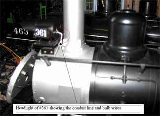
The wires for the headlight bulb run out the back of the housing near where the electrical conduit enters and then down through the top of the smoke box. These wires join the wires from the marker lights which run through the side of the fixture then through the front of the smoke box. Separate the wires into pairs and remove the set for the headlight from the group. You may now remove the headlight wires from the smoke box and the headlight housing with the bulb inside may be set aside.
If this is an early Accucraft loco there is one or possibly two constant lighting circuits inside the smoke box. Look for the leads from the boiler running to the constant light circuit. You will need to tap into those leads for the headlight. The constant lighting circuit is mounted to the large screw that runs from underneath the loco where the front pilot truck is located up through the cylinder saddle and through the bottom of the smoke box. There is a crescent shaped threaded piece along with a couple of nuts securing the front of the loco together along with mounting the constant lighting circuits. You may need to remove one of the nuts to remove the constant lighting circuit to reach the main input leads. Taping into these leads will provide the necessary power for the Evans LED circuit. Again please refer to the previous photo showing the inside of the smoke box on the #461.
On the newer locomotives, the brown and blue leads run from the plug to the tender underneath the cab of the locomotive to the lights in the smoke box. From the factory these are wired to a 1.5 volt constant lighting circuit in the tender. {see earlier photo of the circuit board in the tender.] As I mentioned earlier I switched these wires in the tender to the full power output on the circuit board, (which is marked on the board). Thus there is the full power running to the front of the loco. Wiring the brown and blue leads to the input leads of the Evans Design circuit will provide the power for the new LED headlight. I also added my own constant lighting circuit here in the smoke box for the marker lights and cab light.
Returning to the headlight, remove the headlight wires from the loco smoke box and using a small metal rod push the headlight lens out using the hole for the electrical wires. I used a thin brass rod for this by placing the rod in a vise to keep it from bending. /p>
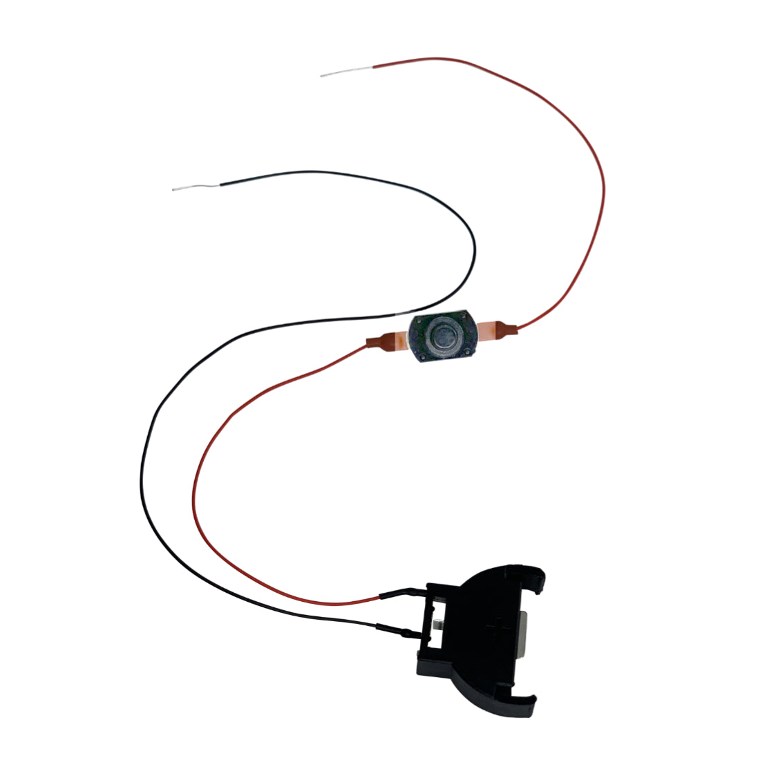
Now you may remove the light bulb by pulling the bulb and wires through the front of the housing. The Evans Design kit contains two components: the LED with two leads and the circuitry with 4 leads. The LED needs to be prepared for the headlight. Because the LED and its metal leads are too long the leads are bent using two needle nose pliers. One set of pliers are placed at the back of the plastic LED to protect it and the wire leads from being broken. The second set of pliers is used to bend the wire lead in a corkscrew. Here is a photo of the finished LED.
Next, two thin plastic disks were made to fit inside the headlight. The first one was to be placed in the back of the housing to insulate the wire leads from the possibility of touching the metal housing and causing a short. It has a small hole in the center for the two wires to exit the housing. The second disk is used to position the LED in the center of the headlight and hold it in place. This hole was drilled at 5 mm to accommodate the LED.
After cutting out the 11/16 inch diameter disks the LED was installed in the headlight housing. Be careful to note the positive wire on the LED. Here is the headlight with the LED installed.
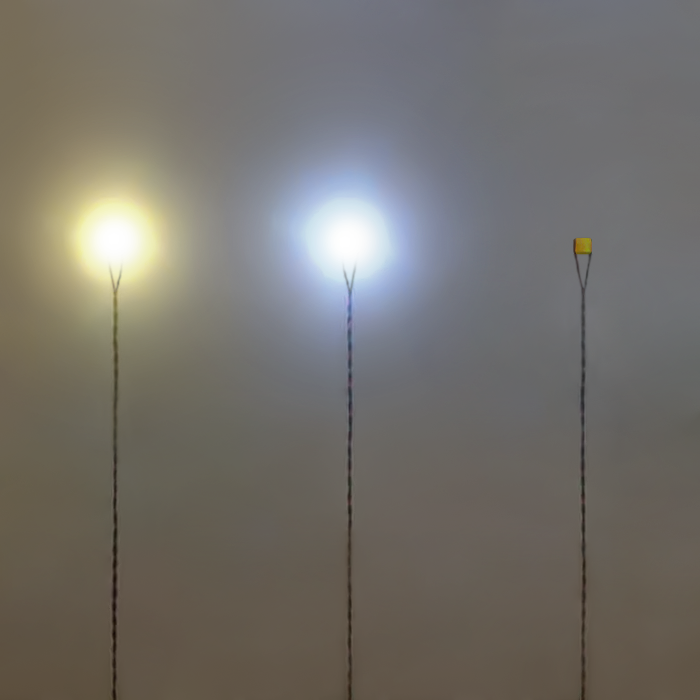
Run the wire leads through the top of the smoke box and reinstall the headlight using the five 2 mm screws you saved. Attach the positive wire from the LED to the red wire of the Evans Design circuit and the other wire to the black wire from the circuit. As mentioned earlier depending on the locomotive the two other black wires from the Evans circuit module should be wired to either the input leads to the constant lighting circuit (older locos), or to the brown and gray wires of the newer ones. You may want to place some electrical tape around your connections or use heat shrink tubing to insulate the connections. Now reinstall the smoke box front either by just pushing it on or pushing it on and reinstalling the two 2 mm screws. This should complete the modification. Here are a couple of poor shots to capture the effect of the LED without using a flash. The LED is much brighter and has a focused light on the track compared to the marker lights.
